


Get in Touch
Thank you for reaching out to VOLANSYS! Please help us with your details. Our team will contact you shortly.
Visit Us: USA
2890 Zanker Road,
Suite 200, San Jose,
CA – 95134
+1 510 358 4310 (USA)
Suite 200, San Jose,
CA – 95134
+1 510 358 4310 (USA)
Visit Us: India
4th floor, Aurelien Commercial Building
Near LJ Campus, SG Highway
Ahmedabad Gujarat, 382210
+91 79 4004 1994 (IND)
+91 79 4004 1994 (IND)
Mail Us:
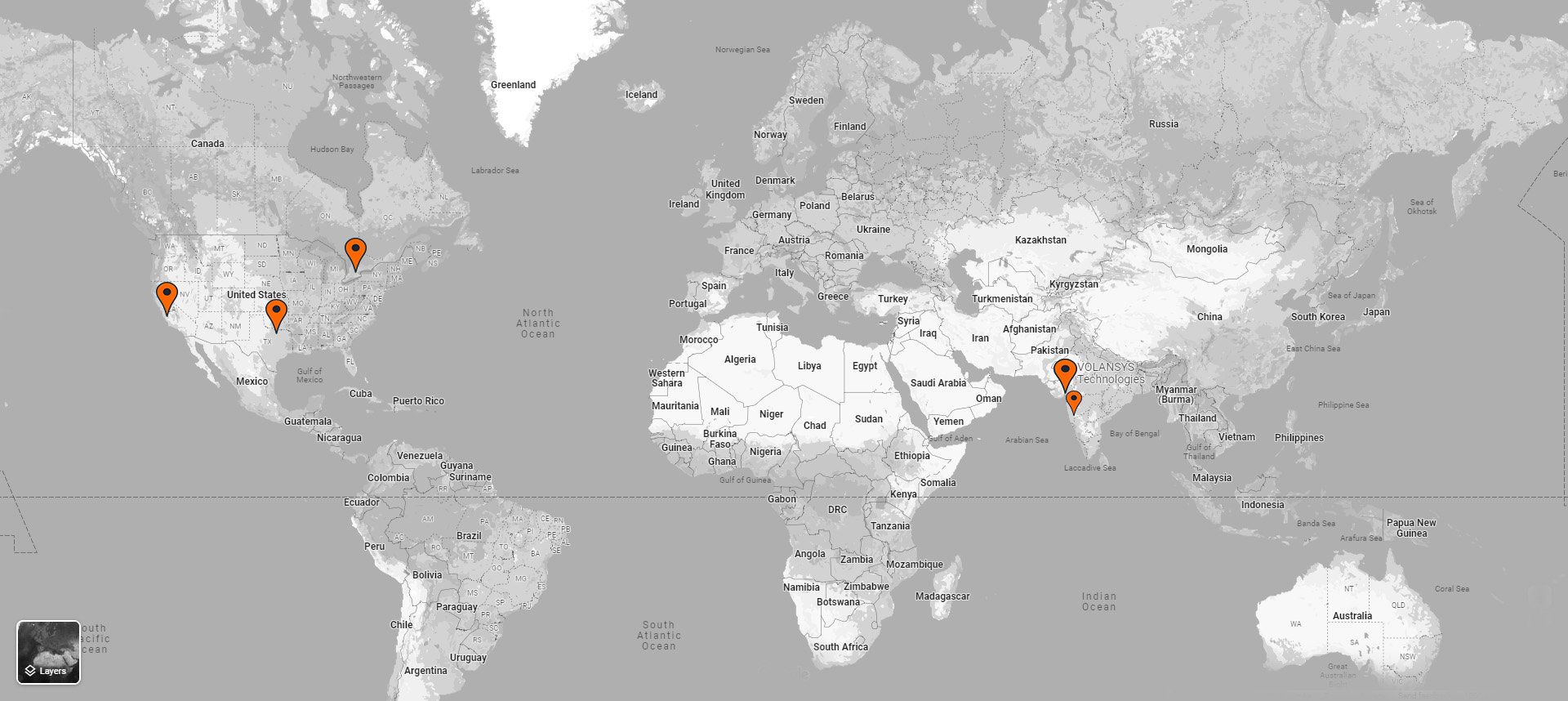
Our Global Presence
USA
Canada
GTA
380 Wellington Street
Tower B, 6th Floor,
London, Ontario N6A 5B5
+1 519-670-0120
India
Ahmedabad, Gujarat (HQ)
4th floor, Aurelien Commercial Building
Near LJ Campus, SG Highway
Ahmedabad Gujarat, 382210
+91 79 4004 1994
Pune, Maharashtra
c/o Awfis, 1st Floor, Nucleus Mall, Opp. Police Commissioner Office, 1 Church Road,
Pune, Maharashtra – 411001
+91 79 4004 1994